Gas supply systems
Gas supply systems by Schick are custom-designed and manufactured. In line with your requirements, we plan and realise your system jointly with you.
Our gas supply systems are available for the gases liquefied under pressure
Ammonia
Sulphur dioxide
Your benefits
- 100 years’ experience with gases liquefied under pressure
- Almost 60 years’ experience in plant engineering
- Competent advice
- Customised planning and production in line with your requirements
Your request
Provide us with the following key data and you will receive a customised offer tailored towards your needs:
1. Maximum mass or volume flow
(Peak load in kg/h or Nm³/h)
2. Desired supply pressure
(in bar; up to a maximum of 4 bar possible)
3. Estimated average gas consumption
(e.g., in kg per month)
Gaseous vs. liquid withdrawal
In the pressurised gas container, the stored medium, i.e., ammonia or sulphur dioxide, is always present at vapour pressure in two aggregate states for technical reasons: liquid (bottom) and gaseous (top). The appropriate extraction valve is required depending on the type of extraction (liquid, gaseous).
Gaseous extraction is usually applied for smaller gas requirements (up to approx. 5kg/h). The medium evaporates in the pressurised gas container. If withdrawal quantity is too high, the pressurised gas container becomes cold and the pressure collapses.
Liquid extraction is typically used for greater gas requirements (from approx. 5 kg/h). The liquid medium is then converted from a liquid into a gaseous state in one or several electric dry evaporators.
Switching
By default, our gas supply systems involve two batteries, between which switching takes place alternately. Each of the two batteries may consist of one or more compressed gas containers. When the pressure falls below a pre-set value, you will receive an empty message. Switching can take place manually or automatically.
Automatic switching is the optimal solution when uninterrupted gas supply is imperative and the operating effort should be minimal, e.g., at night or on weekends.
Options
The following additional equipment is available on request:
- Redundant design of plant components to increase security of supply
- Gas warning device (required in Germany pursuant to technical regulations), which triggers an alarm and shuts down the system once critical gas concentrations are reached
- In-line filter to protect the downstream plant components against particles
- Pressure monitoring of the safety blow-out line
- Pressure monitoring of the supply line
- Fuse protection of the supply line to safeguard downstream components and systems
- Schick Push ordering system: Automatic reordering of compressed gas containers
- Risk assessment and acceptance of the installation
System control
The electrical control of Schick's gas supply systems can be conventionally designed with push buttons or as a PLC with touch panel.

The optimal choice is conventional control with push buttons and indicator lights when both cost-efficient and robust solutions for hot and demanding operating environments are required.

Our PLC controls have a 15" touch panel and provide clear and convenient operation, particularly for systems with one or several evaporators. Additional benefits are the improved expandability of the gas supply system and the option of integrating the control system into existing process control systems.
Container
If you do not wish to or are unable to construct an enclosure on site, we deliver the supply system entirely assembled, installed in a system container. All of our plant containers have a CE mark as well as the manufacturer's certification according to DIN EN 1090.
Our plant containers are available in one-part or two-part versions. One-part containers are employed if there is already a suitable location for the electrical switchgear available on site. Two-part containers encompass two separate rooms: one room for the gas supply system as well as the compressed gas containers and one for the system control/control cabinet. Spatially separating the gas supply system and the system control is essential for flammable gases (e.g., ammonia) due to explosion protection.
Examples
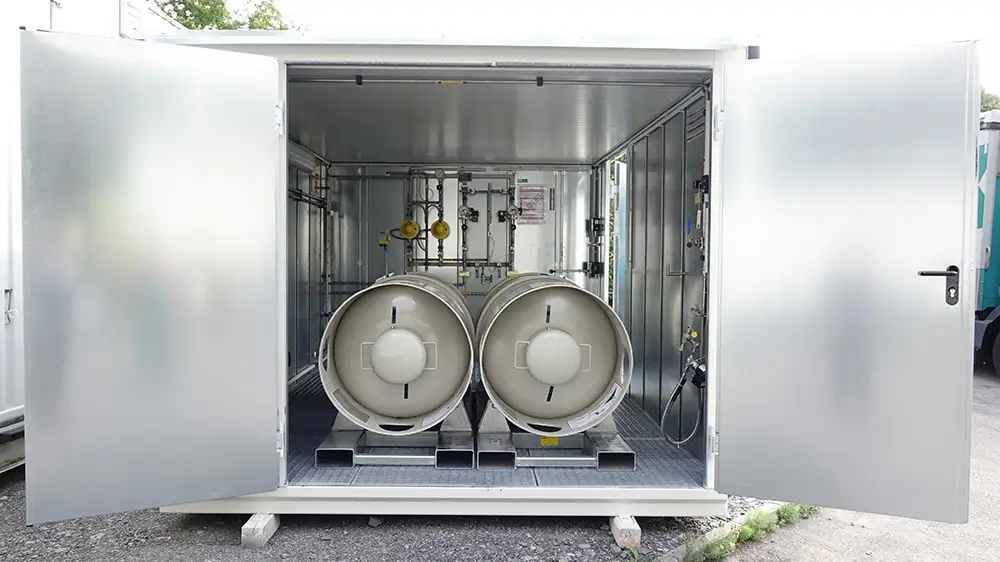
One-part container for an ammonia supply system with gaseous withdrawal and 2 x 1 pressure drums. The control cabinet is installed outside the container.
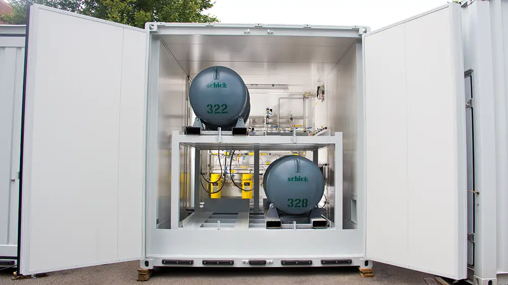
One-part container for an ammonia supply system with liquid withdrawal, two evaporators and 2 x 2 pressure drums. The control cabinet is installed outside the container.
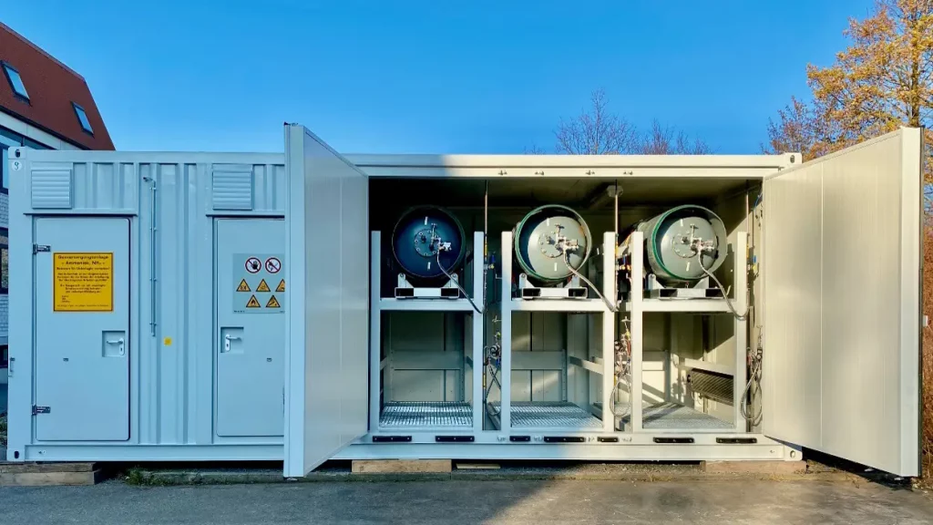
Two-part container with an electrical room for installing the plant control system and a plant room for installing the ammonia supply system with 2 x 3 pressure drums.
Download area
Here you will find all safety data sheets and important information as download (PDF)